Answer
LNG bunkering is governed internationally by the IGF Code (IMO), ISO 20519, and guidelines from SGMF (Society for Gas as a Marine Fuel). Because LNG is stored at cryogenic temperatures (approx. -162⁰C) and poses cryogenic embrittlement, boil-off gas pressure buildup, and explosive vapor hazards, the procedure follows a strict, standardized sequence.
Key Safety Systems & Principles
Prior to commencing operations, key emergency systems must be operational:
- Safety / Ex-Zone Demarcation: A strictly controlled Safety Zone (typically 10–25 meters around the bunkering manifold and tank vents) is established. No hot work, non-Ex equipment, or SIMOPS (Simultaneous Operations) are permitted unless specifically risk-assessed.
- Water Curtain System: Activated over the ship's side shell and deck below the bunkering manifold to protect mild steel hull plating against cryogenic embrittlement in the event of an LNG leak.
- Ship-to-Shore Link (SSL) / ESD Link: Interlinks the receiving ship and supplying facility (truck, bunker vessel, or terminal) via fiber optic, pneumatic, or electric link to ensure synchronized emergency shutdown.
- ESD 1 vs. ESD 2 Logic:
- ESD 1: Shuts down transfer pumps and closes manifold ESD valves automatically (triggered by high tank level, pressure surge, gas detection >20 % LEL, loss of control air, or manual trip).
- ESD 2: Executes ESD 1 and triggers the Emergency Release Coupling (ERC) / Breakaway Coupling to physically disconnect the bunkering hose if the vessel drifts off position.
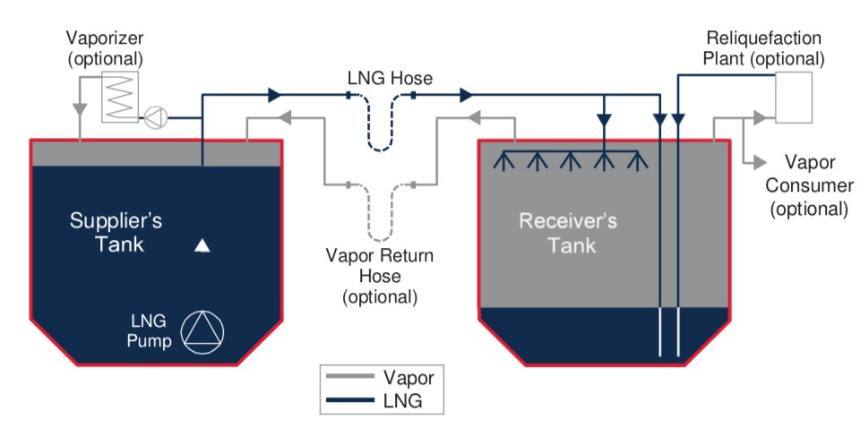
Step-by-Step LNG Bunkering Sequence
1. Pre-Bunkering Coordination & Safety Checklist: Regulatory & Compatibility Handshake.
- Complete the IMO/SGMF Bunkering Safety Checklist between the Receiving Ship Person in Charge (PIC) and Supplier PIC.
- Establish primary and secondary communication channels (handheld intrinsically safe VHF/UHF).
- Set and agree upon maximum transfer rates, maximum allowable tank pressure, emergency shutdown limits, and warm/cool-down protocols.
- Verify active ESD link interconnections and test the Ship-Shore Link (SSL) interface.
- Turn on the hull protective Water Curtain beneath the manifold.
- All important PPEs are worn by the crew directly involved in the operation.
- Spill containment equipments are kept near the bunker station
2. Hose Connection & Pressure / Leak Testing: Establishing Physical Barrier & Integrity.
- Connect the insulated cryogenic liquid hose and vapor return hose using dry-disconnect couplings or bolted flanged connections with insulation flange rings (to prevent galvanic/stray current arcs).
- Attach the safety lanyard for the Emergency Release System (ERS).
- Pressure Leak Test: Pressurize the hose/manifold with N2 up to system working pressure (typically 5–10 bar) and test all joint connections using approved leak-detection spray.
3. Line Cool-Down Phase (Chilling Down): Preventing Thermal Shock & Stress Fracture.
- Never pump liquid LNG at full rate into a warm line.
- Slowly crack open the LNG supply valve to introduce cold LNG vapor / a small trickle of liquid into the hose and manifold.
- Allow the lines to cool down gradually at a controlled rate (typically max 2-5⁰C/min) until the manifold line temperature drops below -130⁰C to -150⁰C.
- Observe frost formation on lines; monitor line pressure and thermal contraction movement on expansion bellows.
4. Bulk LNG Transfer Phase: Continuous Monitoring of Flow, Pressure, and BOG.
- Open receiving fuel tank inlet valves (top spray, bottom fill, or combined depending on tank pressure).
- Start supplier LNG pumps at low capacity; verify pressure stability and check for leaks at dry-break couplings.
- Increase pump speed step-by-step up to the agreed maximum bulk transfer rate.
- Vapor Management: Control receiving tank pressure by splitting flow between:
- Top Spray: Condenses boil-off gas (BOG) inside the tank vapor space to lower pressure.
- Vapor Return Line: Vents excess BOG back to the bunker supplier / facility.
- Continuously monitor tank volume, filling limit (typically 85-95% max filling limit as per IGF Code), temperature profile, and annulus vacuum pressure (for C-type tanks).
5. Post-Transfer Line Draining & Inerting: Clearing Residual Cryogenic Liquid & Gas.
- Stop bunkering pumps upon reaching the target ullage/volume. Close main manifold liquid valves.
- Line Blowing / Stripping: Inject high-pressure Nitrogen (N2) gas from the supplier side to push all remaining liquid LNG inside the bunkering hose into the ship's receiving tank.
- Line Purging: Purge the empty bunkering hose with N2 gas to remove residual hydrocarbon vapor until hydrocarbon content is < 1% LEL.
- Allow the line temperature to warm up above cryogenic limits before disconnecting.
6. Disconnection & Final Documentation: Restoring Safety Boundaries.
- Disconnect the bunkering hose / arm and re-install blank flanges with fresh gaskets and torqued bolts.
- All the FFA and pollution prevention equipment are kept back
- Disconnect ESD / SSL cable and earth grounding cables.
- Deactivate water curtain and reset ESD safety logic.
- Complete and sign the Bunker Delivery Note (BDN)—recording LNG mass, density, gross calorific value (GCV), Wobbe Index, and methane number.